-
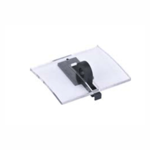
PUSHBUTTON LOCK
The pushbutton lock is to lock the circuit breaker by a transperant conver blocks so as to
prevent the breaking button and the making button of the circuit breaker from misoperation
and guarantee the reliable running of the circuit breaker. -
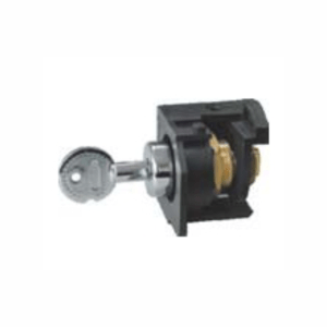
BODY LOCK
• A key lock includes four types. The latter two are applied to 2 input and 1 connect power
distribution system:
– Random lock
– One lock and one key
– Two locks and one key
– Three locks and two keys
Note: When the user separately purchases the key lock for installation, the panel needs to be
opened with a hole opener, and the hole opener is provided by the user.
Hole diameter: NXA16:021mm NXA20-63:024mm
-
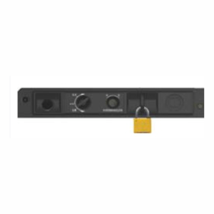
SAFETY SHUTTERS PADLOCK
• The padlock is prepared by users. Diameter of the lock is no more than $5mm. when a circuit breaker body is at the disconnected or test part, the safety shutters automatically block access to the disconnecting contact cluster.
“Disconnected” position padlock
After the chassis and body are locked at “Disconnected” position by a padlock, the
racking-handle cannot be inserted into racking-handle entry, and then the position
of the body cannot be changed.
Door interlock
Circuit breaker state door interlock
A cabinet door is prohibited to be opened when the circuit breaker is closed.
The cabinet door is allowed to be opened when the circuit breaker is disconnected.
Circuit breaker position door interlock
The cabinet door is prohibited to be opened when the circuit breaker is at the connected
and test part. The cabinet door is allowed to be opened when the circuit breaker is at the
disconnected position. -
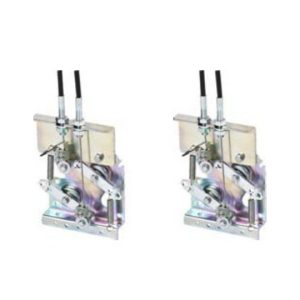
CABLE MECHANICAL INTERLOCK
It can realize the interlock of two horizontal or vertical-installed, three poles or four poles, drawer type or fixed type circuit breaker.
-
AIR CIRCUIT BREAKER
P-020
Accessories: indication contacts
ON/OFF indication contacts
Standard configuration
Breaking capacity
Utilization category
4CO
6CO(for AC of NXA16 only)
Current (A)/Voltage (V) Current (A) / Voltage (V)
VAC(AC-15) VDC(DC-13)
1.3/240, 0.75/415
0.55/110, 0.27/220
“Connected”, “disconnected” and “test” position indication contact
1C0/3
Standard configuration
Breaking capacity
Current (A) / Voltage (V)
Utilization category
VAC(AC-15) VDC(DC-13)
1.3/240, 0.75/415 0.55/110, 0.27/220
Alarming contact
Standard configuration
1CO
Breaking capacity
Utilization category
VAC(AC-15) VDC(DC-13)
Current (A) / Voltage (V) 1.3/240, 0.75/415 0.55/110, 0.27/220
Spring charging indication contact
1.3/240, 0.75/415
0.55/110, 0.27/220
Standard configuration
Breaking capacity
Utilization category
1NO
Current (A)/ Voltage (V)
VAC(AC-15) VDC(DC-13)
1.3/240, 0.75/415
0.55/110, 0.27/220
Note: 1) CO refers to a switch contact, and a one-normally-open and one-normally-closed contact is matched with a common terminal.
2) NO refers to a normally open contact. NC refers to a normally closed contact.
-
SOURCE CHANGEOVER SYSTEMS
Source-changeover systems
• Mechanical interlock
1 normal and 1 replacement
2 incoming and 1 busbar
• Source-changeover controller (with adaptor)
1 normal and 1 replacement: mechanical interlock+2A type controller
2 incoming and 1 busbar: mechanical interlock+3A type controller
N
• Motor-driven mechanism (MO) (Standard configuration)
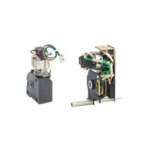
When a circuit breaker is switched on, an motor operation mechanism stores energy automatically, so that when the circuit breaker is tripped, the device can switch on instantly. An energy-storage handle as spare when no auxiliary power supply is provided. -
1600A FRAME MO 2000A 6300A FRAME MO
Characteristics
Power supply
Operation threshold
Frame size: power loss (VA or W)
Motor overcurrent
Charging time
VAC 50/60HZ
220/230/240, 380/400/415
VDC
110, 220
0.85-1.1Us
16: 75W; 20: 85W; 32: 110W; 40: 110W; 63: 150W ≤1min <7s
<2times/min
Operation frequency
• Voltage coils (CC &ST) (Standard configuration) • Closing coil (CC)
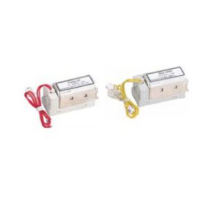
After the energy storage of the motor is completed, the closed electromagnet can be operated and controlled within a range of 10 meters to instantaneously release the energy storage spring force of the operating mechanism to close the circuit breaker. -
Rated Control Power Supply Voltage
Rated Control Power Supply Voltage Us(V) AC 220/230/240
AC 380/400/415
DC220, DC110
AC110 (not available for NXA16)
1600A frame CC&ST
Operation Voltage(V) Close time (ms)
(0.85-1.1) Us <50 NXA16
Power consumption (VA/W) NXA20~63
-
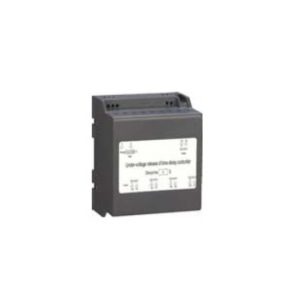
2000-4000A FRAME UVTD
A self-priming under-voltage delay release may be provided for special orders
of NXA20~63. There is no external under-voltage delay controller, and the delay time
is 0.35~7.5s, selectable and adjustable with an accuracy of ±15%.
When the under-voltage release is not powered, the circuit breaker cannot be closed either electrically or manually.
Characteristics of under-voltage release
Rated control power supply voltage Ue(V) Operating voltage (V)
Reliable closing voltage (V)
Reliable not-closing voltage (V)
Power consumption (Inm=1600A/Inm=2000A~6300A)
Ac110. AC220/230/240. AC380/400/415 (0.35~0.7)Ue
(0.85~1.1)Ue
≤0.35Ue
20VA/48VA (W)
N -
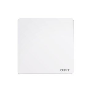
1-gang 1-way switch 10AX 250V
This is a simple, virtual product.
₦1,602.481-gang 1-way switch 10AX 250V
₦1,602.48 -
1-gang 2-way switch 10AX 250V
Model Number: G NEW2-M0020X
Description: 1-gang 2-way switch 10AX 250V
Packing Quantity (pcs/ctn): 120
Carton Dimension (mm): 390X370X302
₦1,748.161-gang 2-way switch 10AX 250V
₦1,748.16 -
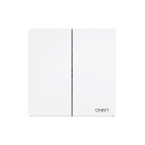
2-gang 1-way switch 10AX 250V
Model Number: G NEW2-M0030X
Description: 2-gang 1-way switch 10AX 250V
Packing Quantity (pcs/ctn): 120
Carton Dimension (mm): 390X370X302
₦1,893.842-gang 1-way switch 10AX 250V
₦1,893.84

